- Raspberry pi zero w pinout spi how to#
- Raspberry pi zero w pinout spi install#
- Raspberry pi zero w pinout spi serial#
- Raspberry pi zero w pinout spi update#
- Raspberry pi zero w pinout spi software#
Io.setup(led2, io.OUT) -The GPIO pin 22 is now configured to an output control. Io.setup(led1, io.OUT) - The GPIO pin 27 is now configured to an output control. Led2 = 22 - It sets the value 22 to the led2 variable. Led1 = 27 - it sets the value 27 to the led1 variable. This implies that instead of specifying the physical pin numbers, you'll use the GPIO numbers for the pins you want to control. Io.setmode(io.BCM) - This changes the GPIO pins' specification mode to Broadcom SOC channel number (BCM). In this case, you'll use it to stop the code for a few seconds. Import time - Several time-based functions are available in the time library. Import RPi.GPIO as io - This will allow you to import the RPi.GPIO library, allowing you to control the GPIO pins. #!/user/bin/python - This line lets you run this code without typing Python before the filename Now, you can write the Python code for blinking LED in terminal window.
Raspberry pi zero w pinout spi install#
You can install this package in raspberry pi zero W using the below command. This package is necessary to access the GPIO pins of Raspberry Pi zero W. You have to install the RPi.GPIO package.
Raspberry pi zero w pinout spi update#
Now, you need to update package version of Raspberry Pi using below command. Then you need to log in and open a terminal window. First, you'll need to boot up the Raspberry Pi Zero. Here, we are going to explain all code line by line. You can see actual hardware connection in below image.Ĭode explanation for Blinking LED using Pi zero W We have used two 220- ohm resistors to drop voltage at positive terminal of LED. Here, we have two LEDs, the positive terminal of red LED is connected with GPIO 27 (pin 13) and positive terminal of yellow LED is connected with GPIO 22 (pin 15) and negative terminal of both LEDs are connected to ground pin (pin 6) of Raspberry Pi zero W. In the image below you can see the circuit diagram of the LED blinking hardware setup. You’ll need following hardware to complete the project: You'll do this by lighting an LED with the GPIO IO pins. The simplest connection that you can make to the GPIO (general purpose input output) on Raspberry Pi zero w is to connect to a pin so that you can send a simple digital output voltage. Here, we are going to blink two LEDs using GPIO pins. In the upcoming Raspberry Pi zero W tutorials, you'll learn more about these dedicated functions. In the below image, you can see some important functions that have been assigned to the pin. GND- GND (Ground) pins are pins in your circuits that offer electrical grounding.

SPI - Hardware communication is also done via SPI (Serial Peripheral Interface Bus) pins, although with a different protocol. I2C - I2C pins are used to connect and communicate with external modules that are I2C compliant.
Raspberry pi zero w pinout spi serial#
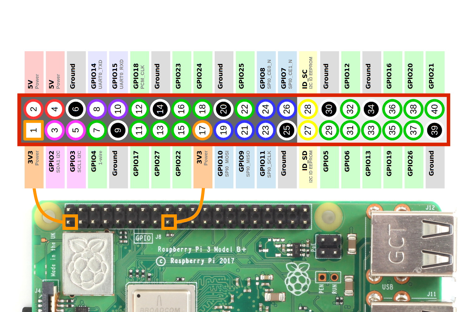
UART- For serial communication, UART (Universal Asynchronous Receiver/Transmitter) pins are utilized. Power- 5V and 3.3V pins are used to give 5V and 3.3V power to external module. In the table below, the various categories are described. The remaining pins have different functions. Each pin on the 40-pin header has a specific purpose. Here, you can see a list of all 40 pins of Raspberry Pi Zero W and their connection to Raspberry Pi zero. On the Raspberry Pi Zero W, pins 1 and 17 supply 3.3 volts pins 2 and 4 supply 5 volts, while pin 9, 25, 39, 6, 14, 20, 30, and 34 are all attached to ground. The GPIO header on your Raspberry Pi has a total of 40 GPIO pins.

GPIO pins are general-purpose pins that can be used to switch external devices on and off, such as LEDs.
Raspberry pi zero w pinout spi software#
Software configurations will be necessary for GPIO pins to work. In essence, GPIO allows our Raspberry Pi to communicate with a wide range of external components, making it useful for projects ranging from a weather station to a self-driving robot. It enables these devices to control external components such as rotors and IR transmitters (output) as well as receive data from sensor modules and switches (input) (input).

GPIO (General Purpose Input Output) is a standard interface for digital input and output found on microcontrollers and SBCs.
Raspberry pi zero w pinout spi how to#
So lets discuss the basics of the GPIO (general purpose input output) pins and learn how to get started with physical computing and GPIO using Python programming.

In our previous tutorial Getting Started with the RASPBERRY PI ZERO, we had an overview Raspberry Pi zero W and setup the Pi Zero. In this tutorial we are going to design a simple LED circuit and control it with the Raspberry Pi Zero W by connecting the circuit to its GPIO pins.


 0 kommentar(er)
